Onboard System
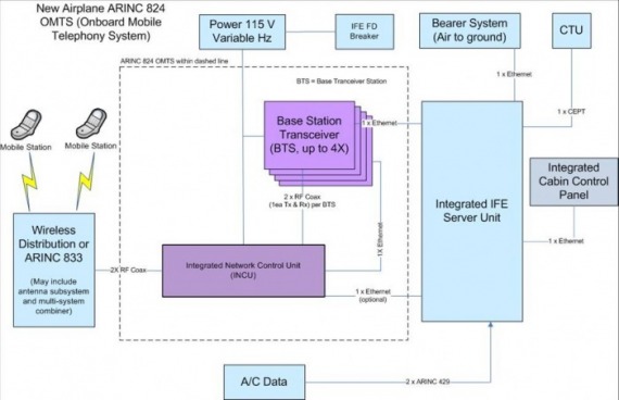
The OMTS portion of the mobile telephony system is found within the dashed lines in the figure below. The NCU (Network Control Unit), BTS (Base Transceiver Station) and Combiner are part of it.
Interfaces and other system units depicted outside of the dashed line are for reference only and may be addressed in other resources.
Base Transceiver Station (BTS)
The OMTS Base Transceiver Station (BTS) enables the use of cell phones on aircraft, and acts as a miniature cell tower. The BTS communicates to the on-board cell phones to (1) offer on-board services (voice, text, GPRS, etc.) and (2) manage the power of the cell phones connected to the BTS. The transmissions will typically occur in a GSM format, and will follow all GSM protocol. The BTS unit receives the RF signal from the cell phones and via the INCU. The BTS unit then demodulates the RF signals and decodes the digitized data being sent from the cell phone. The GSM protocol is then be converted into an IP protocol and provided to the server unit for buffering, control, and interfacing with the terrestrial and satellite RF transmission systems. The media between the BTS and the server unit is an Ethernet.
Integrated Network Control Unit
The Integrated Network Control Unit (INCU), made up of a Network Control Unit and an RF Combiner, prevents on-board CMRS Mobile Stations (MS) from transmitting and therefore registering with terrestrial base stations.
The NCU prevents mobile stations from transmitting by masking all possible cellular channels with an RF signal powerful enough to overcome possible signals received in the cabin from terrestrial base stations. Those onboard mobile stations that are technically capable of roaming onto the OMTS (e.g. GSM phones will be able to roam onto a GSM-supported OMTS) are then able to communicate with the onboard BTS while those mobile stations (cell phones) that cannot are prevented from transmitting. The NCU includes software to manage the operation of the NCU RF bands with flight phases, the country being flown over, and altitude.
The RF Combiner is designed to ensure that the transmitting RF signals from the NCUs and multiple BTS’s are combined in such away to ensure that inter-modulation products are minimized, to reduce in cabin electromagnetic interference that is out of band, and that the receivers of the BTS’s maintain their sensitivity.
General description of the OMTS associated units
Server Unit
The server unit hosts part of the OMTS software. The OMTS software may include (1) Base Station Controller (BSC) functionality, (2) management of the NCU RF bands with flight phase, country over flown and altitude, (3) the management of the interconnection to the ground segment via the Bearer System and (4) Operation and Maintenance. It may also connect to the control panel, CTU, aircraft data systems and cockpit panel.
Integrated Control Panel
The integrated control panel is the user interface to the OMTS for the cabin and maintenance crew. The control panel is usually located in the cabin. The control panel indicates the status of the system. The control panel allows the cabin crew to control the system and change various settings of the system (e.g. enable a system reset, or change the level of mobile communications). The maintenance crew can also connect to the control panel via a standard laptop and switch the system to maintenance mode in order to execute centralized system testing, centralized data and configuration loading.
Mobile Station
The mobile station is the cell phone that the passenger will bring on board the aircraft. All cell phones that follow a mobile/cellular communication standard with the onboard frequencies utilized by the BTS can be used for communication. Passengers with other cell phones not utilized by the BTS could use all other functions on their device except the transmitting communication functionality.
Aircraft (AC) Data System
This system provides the OMTS system with aircraft related data, e.g.: Altitude, longitude, latitude and city pairs. The OMTS may interface to the ARINC 429 airplane systems bus containing this data, and it provides a read-only interface to receive the data. The OMTS may alternatively receive the aircraft positional data using the Server Unit.
Wireless Distribution
The wireless distribution system distributes the RF signals in the cabin. The wireless distribution system is comprised of an antenna subsystem that will provide receive and transmission capabilities between the OMTS and passenger cell phones. The wireless distribution system supports a frequency band from 400 MHz to 6 GHz. The OMTS may alternatively be connected to a Universal Wireless Distribution System.
Bearer System
The bearer system is independent from the OMTS system. It provides the communication link between the aircraft and the Ground Segment for the OMTS voice and data services. The OMTS can be connected to the Server unit or directly to the bearer system utilizing industry RF standards, via Ethernet, or indirectly to the Bearer System via an ISDN channel in the CEPT-E1 through the Server or the CTU.
